

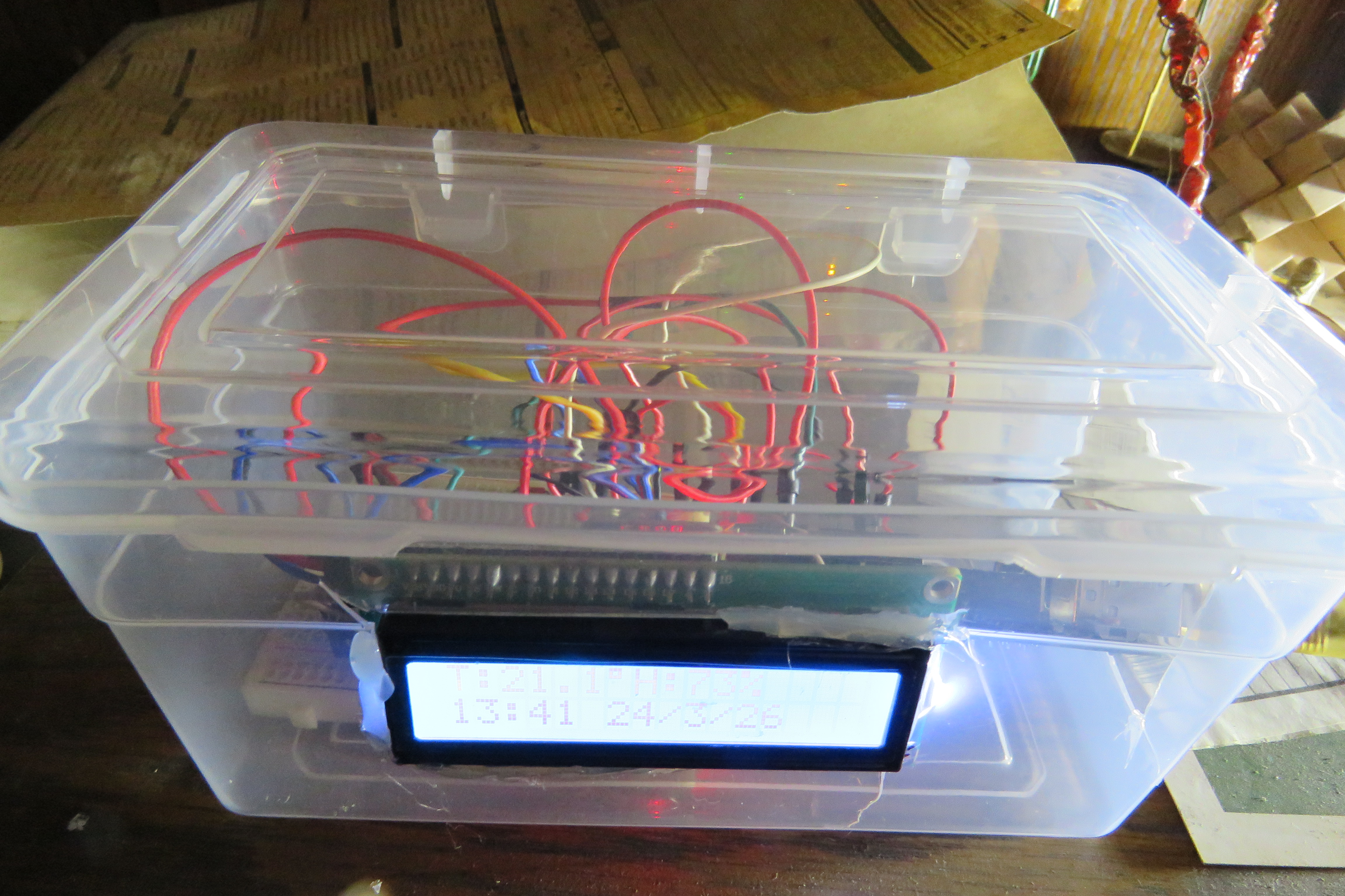
I have been intending to build a clock with Arduino for a long time, mostly because I do need a clock, but it also seems like an easy build using the parts often bought in kits. I tried multiple examples I found online but could not get any working properly, so I made this code from what I found. The time can be set using the code. For fabrication I am dumping everything, breadboard included, into a clear plastic box, but I will potentially do a further post about using a prototype circuit board.
Parts you will need:
| Arduino Uno (rev 3) | 1 | Buy on RS |
| RTC module (Ds3231) | 1 | Find on AliExpress |
| Temp/Humidity sensor (DHT11) | 1 | Buy on RS |
| LCD Screen (LCD 1602) | 1 | Get it on AliExpress |
| Jumper cables | Buy on Temu | |
| Breadboard | 1 | Buy on RS |
| Plastic box (~16x9x9cm) | 1 | West Pack (SA) or Any cheap plastics shop |
Multi-function clock code
Copy and paste the code below into Arduino Code or other IDE and upload it to the Uno. For the first time upload set the time in the first loop of the code inside the if (!TIMESET) condition. Save any changes to the code and upload to the Uno. After the time is set and the code uploaded, change the TIMESET Boolean to true, save and upload the code again. As long as the RTC chip has a battery the time will be correct even when the Arduino is not powered.
#include <Wire.h>
#include <LiquidCrystal_I2C.h>
#include <DHT.h> // DHT sensor library from Adafruit
#define DHTPIN 3
#define DHTTYPE DHT11
bool TIMESET = false;
DHT dht(DHTPIN, DHTTYPE);
LiquidCrystal_I2C lcd(0x27,16,2); //0x27 is the LCD Address
#define DS3231_I2C_ADDRESS 0x68
byte bcdToDec(byte val){ return( (val/16*10) + (val%16) ); }
byte decToBcd(byte val) {
return ( (val/10*16) + (val%10) );
}
void readDS3231time(byte *second,byte *minute,byte *hour,byte *dayOfWeek,byte *dayOfMonth,byte *month,byte *year){
Wire.beginTransmission(DS3231_I2C_ADDRESS);
Wire.write(0); // set DS3231 register pointer to 00h
Wire.endTransmission();
Wire.requestFrom(DS3231_I2C_ADDRESS, 7);
// request seven bytes of data from DS3231 starting from register 00h
*second = bcdToDec(Wire.read() & 0x7f);
*minute = bcdToDec(Wire.read());
*hour = bcdToDec(Wire.read() & 0x3f);
*dayOfWeek = bcdToDec(Wire.read());
*dayOfMonth = bcdToDec(Wire.read());
*month = bcdToDec(Wire.read());
*year = bcdToDec(Wire.read());
}
void setDS3231Time(byte *second,byte *minute,byte *hour,byte *dayOfWeek,byte *dayOfMonth,byte *month,byte *year) {
Wire.beginTransmission(DS3231_I2C_ADDRESS);
Wire.write(0); // Set register pointer to 00h
Wire.write(decToBcd(*second));
Wire.write(decToBcd(*minute));
Wire.write(decToBcd(*hour));
Wire.write(decToBcd(*dayOfWeek));
Wire.write(decToBcd(*dayOfMonth));
Wire.write(decToBcd(*month));
Wire.write(decToBcd(*year));
Wire.endTransmission();
}
int backlightPin = 3;
void setup(){
Wire.begin();
Serial.begin(9600);
lcd.backlight();
lcd.init();
pinMode(backlightPin,OUTPUT);
analogWrite(backlightPin,50); // For External Backlight Control
dht.begin();
}
void loop(){
lcd.clear();
byte second, minute, hour, dayOfWeek, dayOfMonth, month, year;
if (!TIMESET) {
byte s = 0; // second
byte m = 36; // minute
byte h = 15; // hour 24-hour format
byte d = 1; // day of week 1-7
byte dm = 23; // day of month
byte mm = 3; // month
byte y = 26; // year 2026
setDS3231Time(&s, &m, &h, &d, &dm, &mm, &y);
TIMESET = true;
}
readDS3231time(&second, &minute, &hour, &dayOfWeek, &dayOfMonth, &month, &year);
float humidity = dht.readHumidity();
float tempC = dht.readTemperature();
float tempF = dht.readTemperature(true);
// Check for read failure
if (isnan(humidity) || isnan(tempC)) {
Serial.println("Failed to read from DHT11");
lcd.setCursor(0, 0);
lcd.print("Loading... ");
return;
}
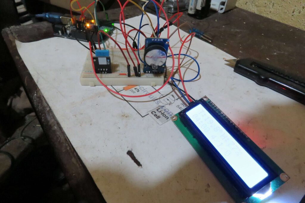
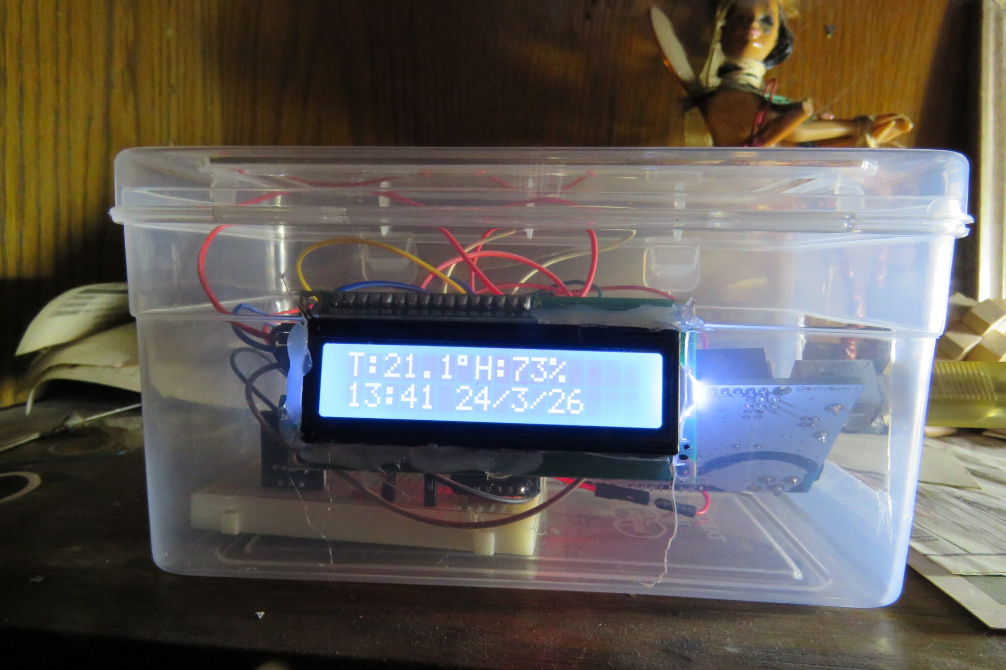
lcd.setCursor(0, 0);
lcd.print("T:");
lcd.print(tempC, 1);
lcd.print((char)223);
lcd.print("H:");
lcd.print(humidity, 0);
lcd.print("%");
lcd.setCursor(0,1);
if(hour<10) lcd.print("0");
lcd.print(hour);
lcd.print(":");
if(minute<10) lcd.print("0");
lcd.print(minute);
lcd.print(" ");
lcd.print(dayOfMonth);
lcd.print("/");
lcd.print(month);
lcd.print("/");
lcd.print(year);
delay(1000);
}
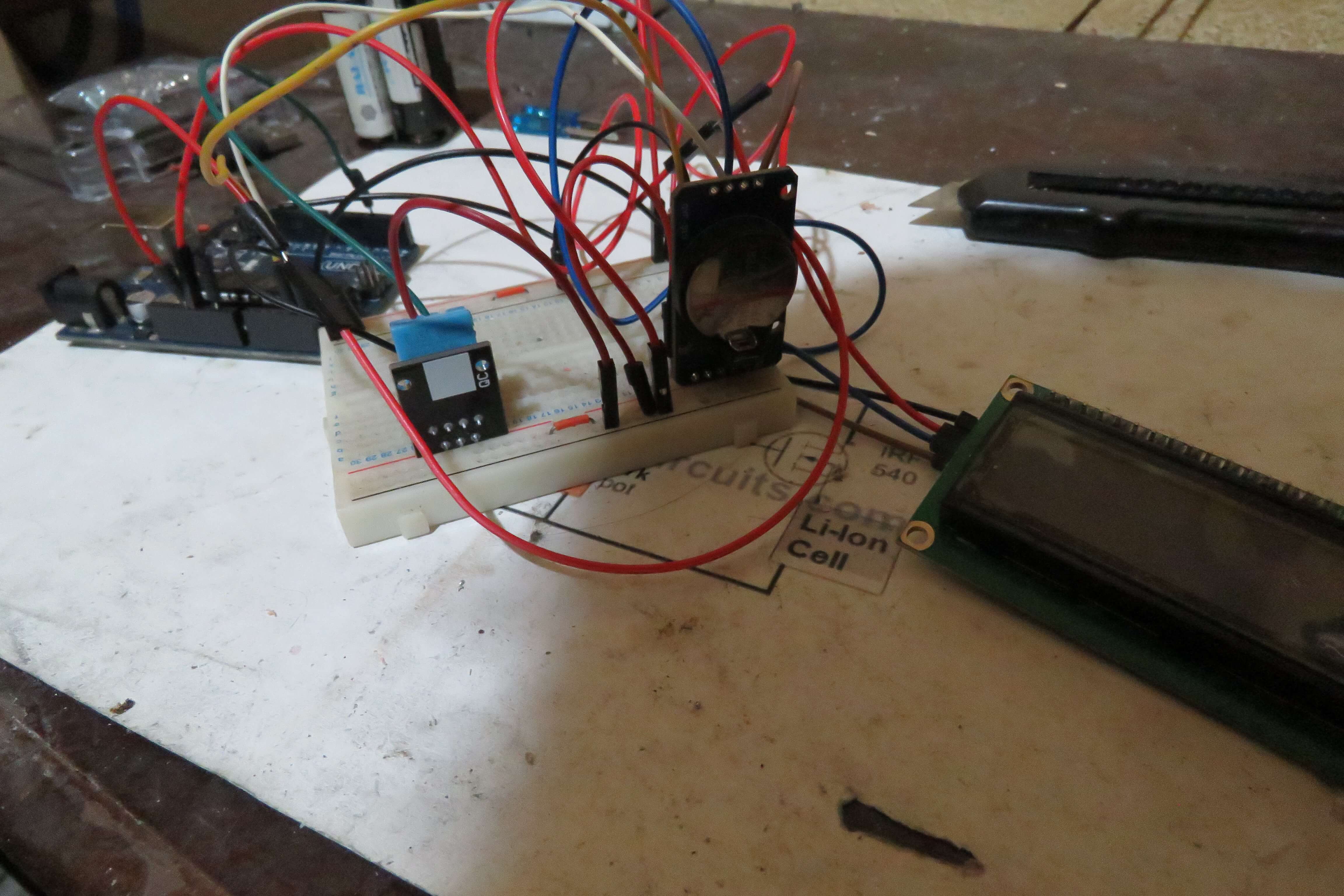
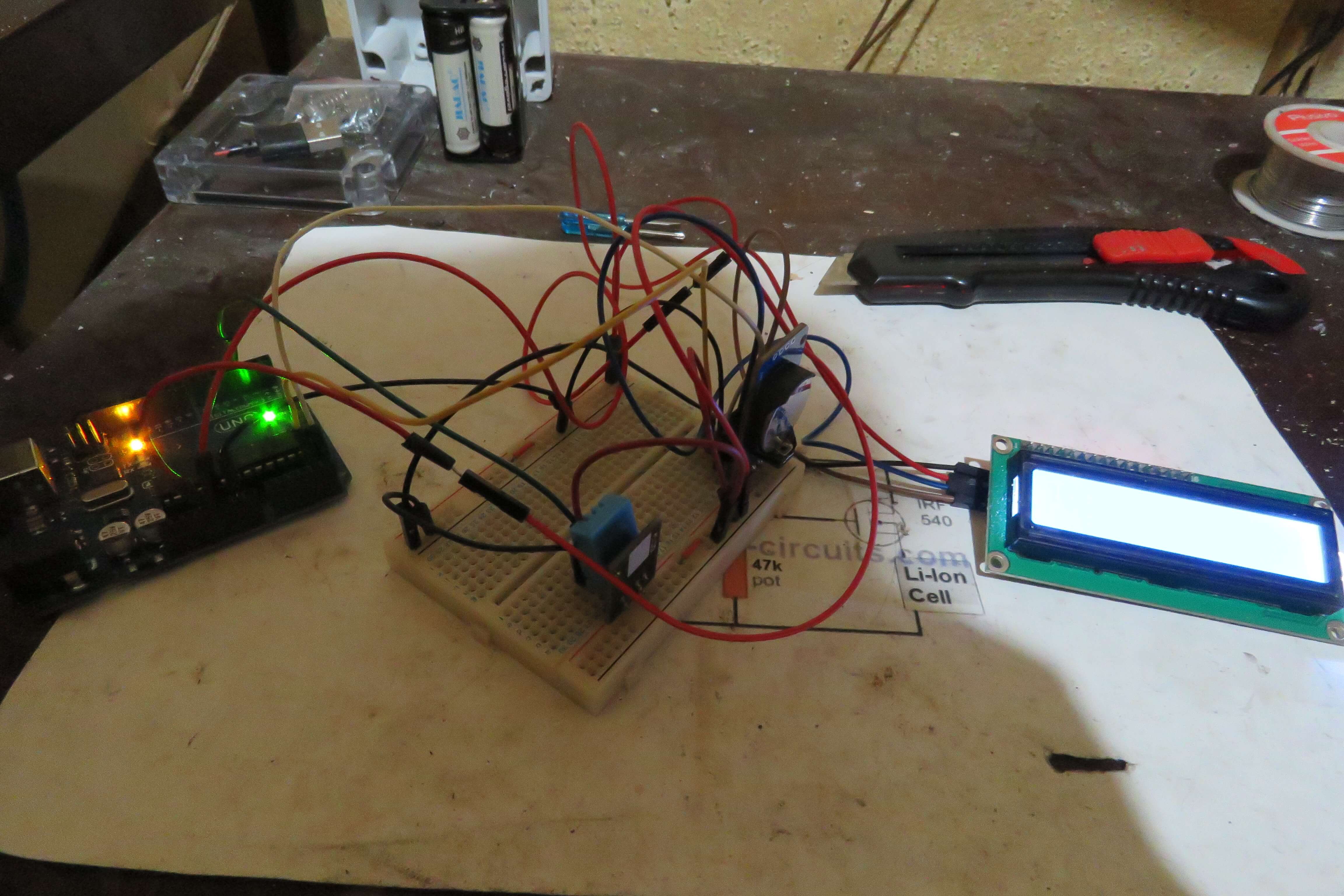
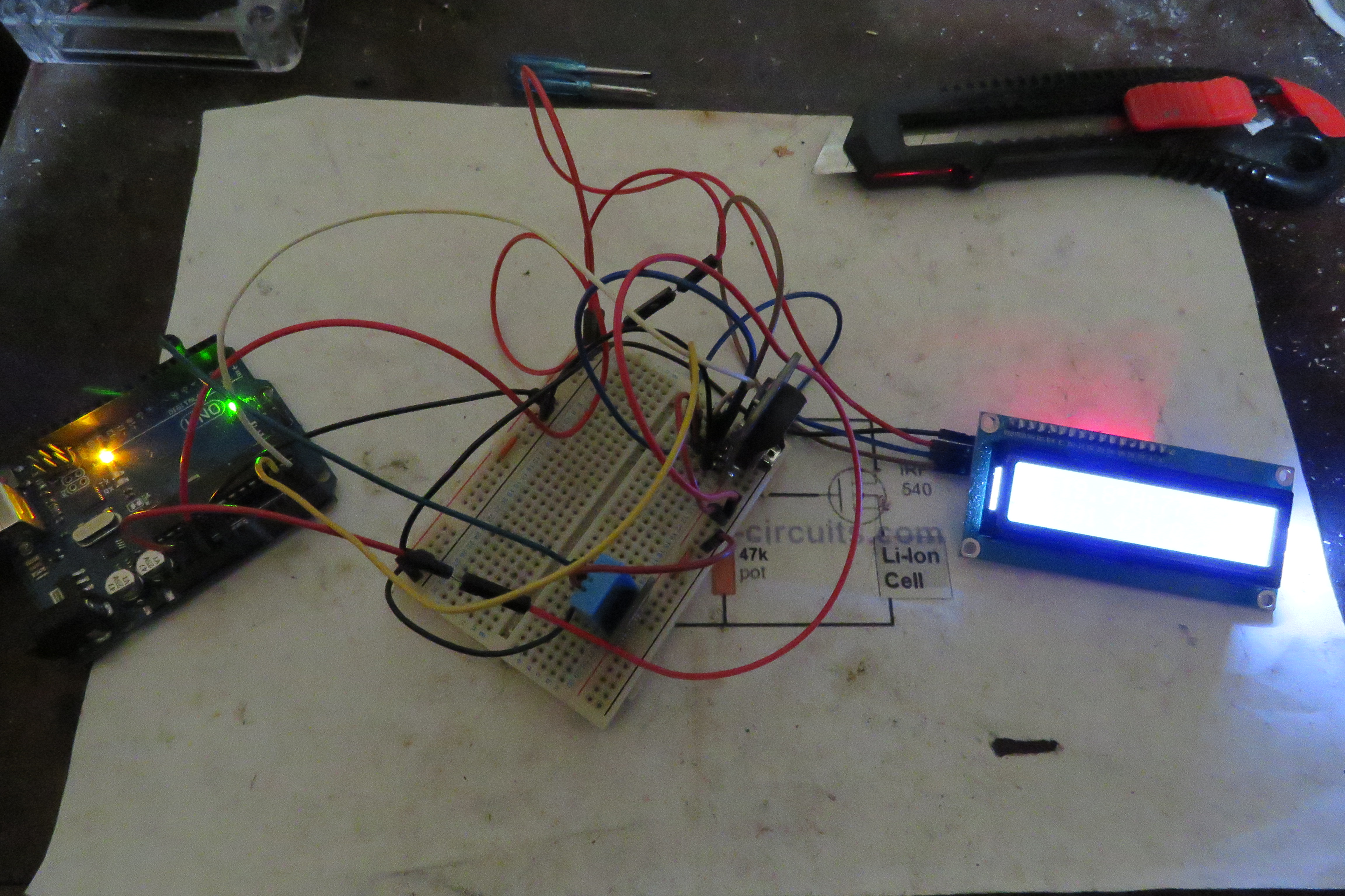
The completed prototype diagram
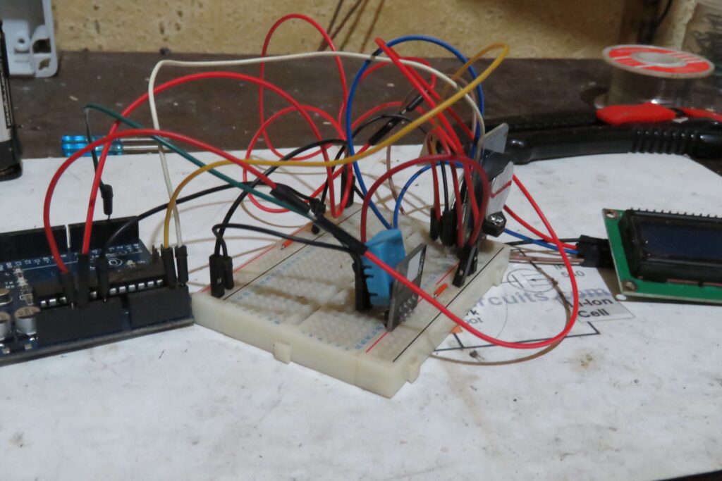
Below is the wiring diagram for the prototype – check that the correct pins are connected in case there are any differences in the diagram to your own components, match the pins by name. The DHT11 breakout board is the temperature and humidity sensor, and RTC DS3231 is the Real Time Clock that will keep the time and date. You should put in a 3V battery (CR2032 or CR2025), otherwise you will have to reset the time every time you un-power the board. The LCD module should have an extension board on the back with 4 pins (c in figure A).
The RTC chip and the DHT are connected to the breadboard. The LCD is connected to the 5V output on the Uno via the breadboard while the RTC and and DHT are connected to the 3.3V. If you have issues with the RTC running slow, you can change to using the 5V instead. In my example the top and the bottom power parts of the breadboard use different voltages but the negative is the same.


Fabrication
Maybe a grandiose term considering. I bought a large clear plastic container from West Pack. I will cut a whole to fit the LCD and a large hole in the side to connect the Uno to USB or DC power. I did try to see how battery power would work but with the LCD backlight on a 9V battery lasted about four hours. It is possible to turn off your backlight, or connect it to use a switch – on my board there are two connected points (a in Figure A), this makes the backlight on permanently. Disconnecting these will turn the backlight off and allow you to control it with code.
It is not important to me for the box to be built strongly. It will sit on my table and won’t be moved much. I am hot gluing the LCD in place and putting the breadboard and Uno loose in the box. If this does not fit your needs, you’re on your own to properly secure everything and drill precise holes to mount the board. There are custom boxes made for this sort of thing, but the one I got cost R20 ($1.20).

Troubleshooting
To troubleshoot the setup, most likely problems are incorrect wiring or using different breakout boards. If you followed the wiring diagram and the clock does not work you should assume the diagram has an error or is different to what you have. Rather follow the pin names on your breakout boards to ensure the correct connections.
I had an issue of the clock being slow – I changed the voltage to 5V for the RTC and changed the 3V battery, and it has fixed the problem. I do not know which of these two corrected the problem, but try both if your clock is slow.
Providing the incorrect voltage to the Uno can also cause issues. Using less than 9V seems to mean not enough voltage goes to the breakout boards. For ease it’s best to use a USB cable or a 12V DC adapter rather than powering through the Vin pin on the Uno.
If your LCD is powered but does not show any text or blocks instead of text, it might be the contrast. You can adjust the LCD contrast by turning the blue potentiometer on the board (b in Figure A). Use a small Philips screwdriver.
If you have parts other than the ones listed or different versions you will need to use the correct libraries for those in the code. Because I am not using a library for the RTC you should only need to change the DHT and LCD libraries. Different parts may also have different pin layouts, so match the pin names when checking wiring.


Hope you build a better clock than I did.
Leave a Reply